Connecting a difavtomat in a single-phase network - diagram and connection procedure
A differential circuit breaker is an electromechanical device that protects the power grid against damage due to short circuits or high loads. In addition, it ensures the safety of people by avoiding electric shock when touching a line that has a leakage current. Thus, it combines the functions of two devices: a circuit breaker and an RCD. Connecting a difavtomat is not an easy task, and in order to perform it correctly, you need to observe safety measures, as well as follow the installation rules. How to connect a difavtomat will be discussed in this article.
Content
Design features of differential automata
As already mentioned, installing a difavtomat in the network allows protection against electric current leaks, overloads and short-circuit overcurrents. This device is combined, and it consists of two main components:
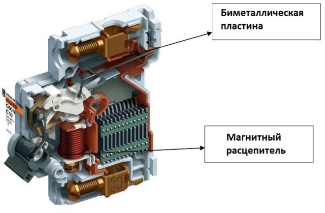
- Circuit breaker with electromagnetic (coil) and thermal (bimetallic plate) releases. The first turns off the power to the line when a short circuit occurs in it, and the second de-energizes the network when a load exceeds the calculated one. AB in difavtomats can have 2 or 4 poles, depending on which network they protect - single-phase or three-phase.
- Residual current device. This element includes a relay, which, during normal operation of the network, is affected by magnetic fluxes of the same strength, not allowing the line to be disconnected. In the event of a leak (electricity leakage to the ground), the uniformity of the flows is disturbed, as a result of which the relay switches with the line de-energized.
In addition to AV and RCD, the machine contains a differential transformer, as well as an electronic amplification element.
Installing a difavtomat in a one- and three-phase network
Before you start connecting the differential machine, you must press the "Test" button on its body. Thus, a leakage current is artificially created, to which the device must respond by switching off. This will make sure that the device is working properly. If the device does not turn off during the test test, it cannot be used.
In household single-phase networks, where the operating voltage is 220V, two-pole RCBOs are installed.
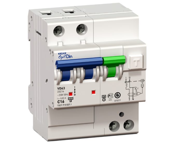
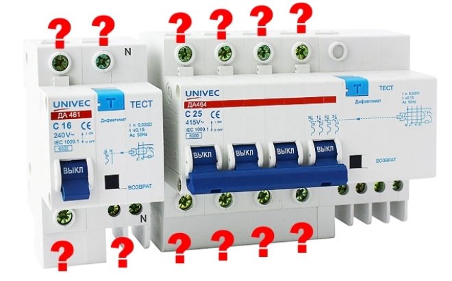
Connecting a difavtomat in a single-phase electrical network requires the correct connection of neutral wires: zero from the load is connected from the bottom of the device, and from the power supply - from the top.
Installation of a four-pole diff. An automatic machine designed to protect a three-phase network, the operating voltage of which is 380V, is made according to a similar principle. It should be borne in mind that a three-phase (four-pole) difavtomat takes up more space in the switchboard than a single-phase one. This is due to the need to install a differential protection unit.
The case of some RCBO types is marked with the 230 / 400V designation. Such a device can be installed in a network with one or three phases. In the second case, these devices are mounted on consumers using only one phase - this can be a group of outlets or individual devices.
Connection diagrams
The basic rule that any circuit for connecting a differential machine must take into account is: RCBOs must be connected to the phases and neutral conductor only of the line or branch for which this device is intended to protect.
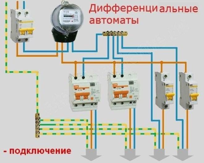
Introductory machine
In this case, the differential automaton in the shield is installed on the input wire. Such a scheme for connecting a difavtomat got its name because the device protects all groups and branches of the network to which it is connected.
When selecting RCBOs for this circuit, it is necessary to take into account all the operating parameters of the line, including the power consumption. This method of connecting a protective device has a number of advantages, which include:
- Savings, since a single machine is installed on the entire network.
- Compactness, as one device does not take up much space in the panel.
The disadvantages of this scheme are as follows:
- When a network failure occurs, the entire apartment or house is de-energized.
- In case of any malfunction, it will take a long time to find and fix it, since you will need to find the branch on which the failure occurred, as well as establish the specific cause of the problem.
Illustrative diagrams for connecting difavtomats in the video:
Individual machines
This connection method provides for the installation of several differential ABs. The installation of a difavtomat is carried out on each separate branch or a powerful consumer. In addition, an additional RCBO is placed in front of the group of protective devices themselves. For example, one device is installed on lighting devices, another is installed on the outlet group, and a third is installed on the electric stove.
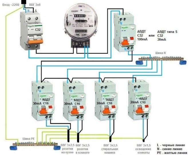
The advantage of this method is the maximum level of security, as well as fairly easy troubleshooting. Its disadvantage is the high costs associated with the purchase of several differential automata.
Difautomat in a circuit without grounding
Not so long ago, the technology of construction of any buildings took into account the obligatory arrangement of the grounding circuit. All switchboards available in the house were connected to it. In modern construction, grounding equipment is optional. In such buildings and the apartments available in them, differential AB must be installed in order to ensure the required level of electrical safety. The difavtomat in such a scheme not only protects the network from malfunctions, but also plays the role of a grounding element, preventing electric current leakage.
Clearly about connecting difavtomats in the video:
What you need to remember when connecting a differential machine?
Regardless of whether a protective device is connected to a single-phase or three-phase network, the following rules must be observed during its installation:
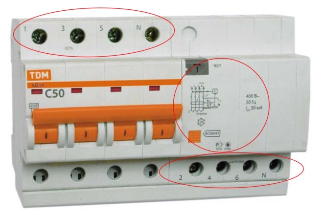
- Power cables should be connected to the upper part of the device, and the wires going to consumers - to the bottom. On the body of most differential AB there is a schematic diagram, as well as a designation of the connectors.
It is very important to correctly connect the difavtomat, since incorrect connection of the conductors is highly likely to cause the device to burn out. If the cables are not long enough, they must be replaced or extended. Alternatively, the device can be turned over on a DIN rail, but in this case, you can get confused during further installation.
- The polarity of the contacts must be observed. All protective devices in accordance with international standards are marked with connectors: for phase - L, for zero - N. The supply cable is designated by the number 1, and the outgoing cable - 2. If the contacts are connected incorrectly, the device will most likely not burn out, but if this will not respond to network problems.
- In many devices, the connection scheme provides for the connection of all neutral conductors to a common jumper. But in the case of differential AV, this cannot be done, otherwise the power will be constantly turned off.In order not to cause malfunctions, the zero contact of each difavtomat should be connected only to the branch that it protects.
Connection procedure
Now let's talk about how to properly connect the RCBO. After you have decided on the installation scheme and purchased everything you need for installation, proceed to the connection. It is done in the following order:
- Examine the case of the device carefully. It should be free of cracks and other defects, as they can cause the device to malfunction.
- Disconnect the power to the home network with a breaker in the distribution board.
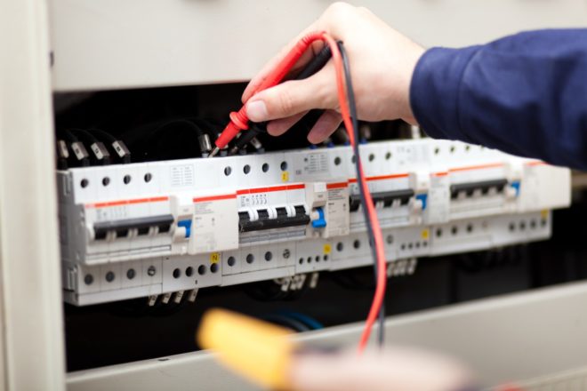
- Use a tester or an indicator screwdriver to check the contacts of the connected consumers to make sure that no voltage is supplied to them.
- Attach the difavtomat to the DIN rail.
- Remove the insulating layer from the ends of the wire to be connected (about 5 mm each). For this, it is most convenient to use side cutters.
- Connect the phase and neutral conductors: from the power wire to the upper terminals of the protective device, and from the protected line to the lower ones.
After that, it remains to turn on the mains power and make sure that the device is working correctly.
The order of assembling the switchboard on difavtomats in the video:
The most common mistakes when connecting RCBOs
If, after connecting the differential machine, it works at the slightest load or does not turn on at all, then its installation was performed incorrectly.
There are several mistakes that inexperienced users most often make when connecting a difavtomat on their own:
- Connection of the neutral wire to the earth cable. In this case, it will be impossible to turn on the RCBO, since it will not be possible to set the device levers to the upper position.
- Connecting zero to the load from the zero bus. With this connection, the levers of the device are set to the upper position, but they are disconnected when the slightest load is applied. Zero should be taken only from the output of the protective device.
- Connecting zero from the device output instead of the load to the bus, and from the latter to the load. If the connection is made in this way, the levers of the device can be set to their original position, but as soon as the load is turned on, the RCBO will cut out. The "Test" button will not work in this case either. The same symptoms will be observed if you confuse the zero connection by connecting it from the bus to the lower, and not to the upper, terminal of the device.
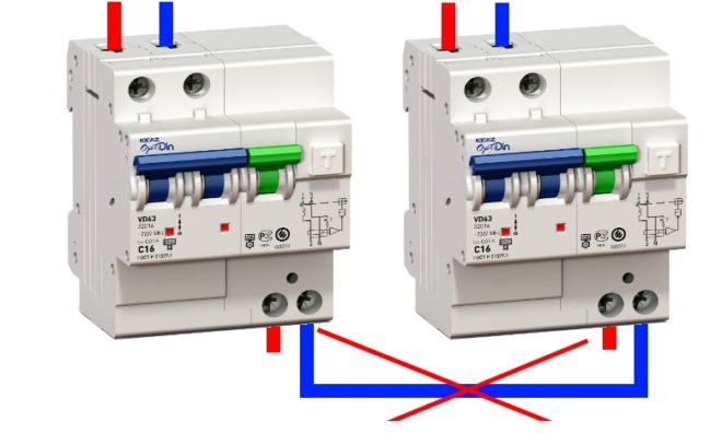
- Mixed up connection of neutral wires from two different RCBOs. In this case, both machines will turn on, the "Test" button on each of them will work correctly, but as soon as the load is connected, both devices will shut down at once.
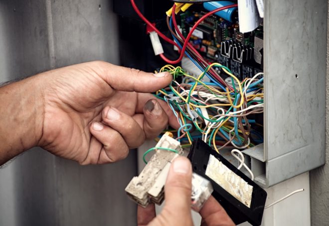
- Connection of neutral wires from two RCBOs. When this mistake is made, the levers of both devices are set to the operating position, but when the load is connected or the "Test" button is pressed on any difavtomat, both will turn off simultaneously.
Analysis of the main connection errors on video:
Conclusion
In this article, we talked about how to properly connect the difavtomat, and also figured out the main mistakes that are made during this procedure. With this in mind, you will be able to install a protective device yourself, and if a mistake is made, you can easily find and fix it.

